3D printing has a charming way of turning a five-minute repair into a six-hour investigation involving calipers, three filament spools, seventeen browser tabs, and at least one mysterious clicking noise. Printed gears are especially good at inspiring this kind of optimism. They emerge from the printer looking precise, purposeful, and ready to run forever. Then the motor starts, the teeth begin meshing, and reality arrives carrying a small bag of plastic dust.
A widely discussed service life study put three common fused-filament materialsPLA, ABS, and PETGthrough controlled gear-wear testing. The experiment produced a clear winner under its test conditions, but its greater value lies in showing why material selection is only one part of designing a reliable 3D-printed gear.
Why Study the Service Life of 3D-Printed Gears?
Plastic gears are hardly exotic. They appear in printers, cameras, toys, automotive assemblies, office equipment, food-processing systems, textile machinery, and countless household appliances. Compared with metal gears, polymer gears can be lightweight, quiet, corrosion-resistant, inexpensive, and capable of running with little or no lubrication.
Traditional plastic gears are commonly injection-molded or machined. Those methods work beautifully at scale, but they are less attractive when someone needs one replacement gear for an old mixer, telescope mount, robot, scanner, or discontinued garage-door mechanism. Tooling costs can make injection molding absurd for a one-off part, while machining may waste material and require equipment that the average home workshop does not possess.
Fused deposition modeling, also called FDM or fused filament fabrication, offers a tempting alternative: model the component, slice the file, load filament, and manufacture the replacement locally. Research into appliance repair has found that this flexibility could reduce downtime and prevent otherwise functional products from being discarded because a small proprietary gear is unavailable. However, printed PLA and ABS do not automatically match the performance of conventional engineering plastics such as molded nylon.
Inside the Gear Wear Experiment
Three familiar materials enter the test rig
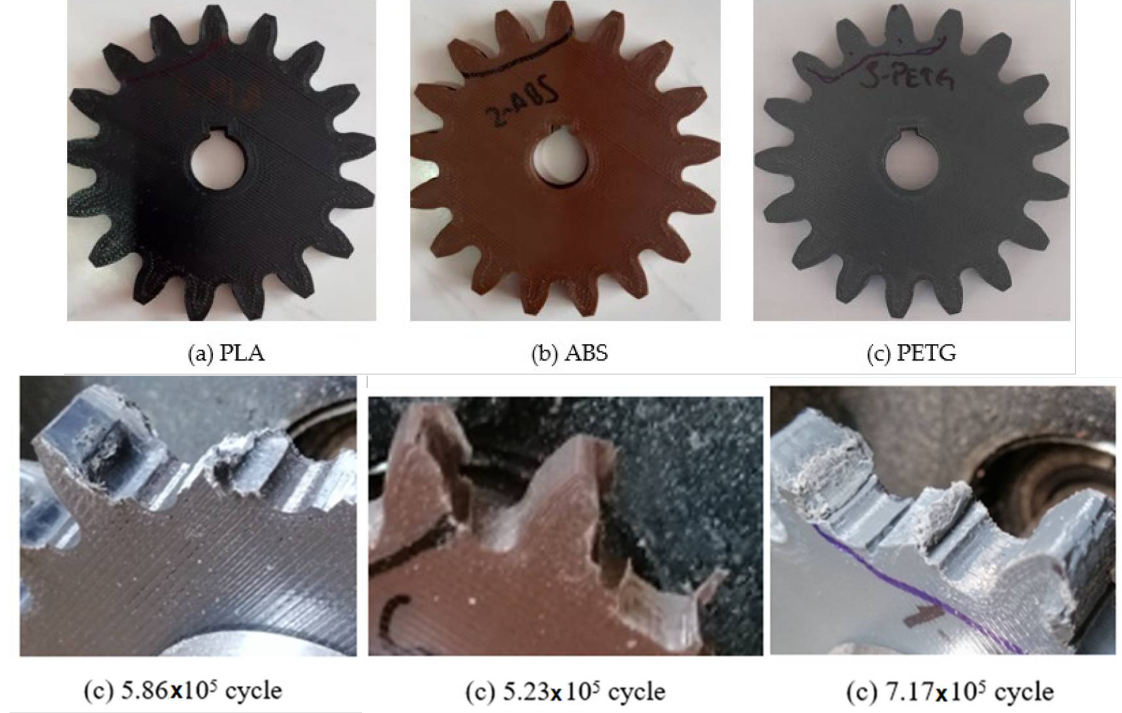
The researchers manufactured comparable spur gears from PLA, ABS, and PETG using an FDM printer. Each polymer gear meshed with a steel gear in an FZG-style testing system capable of controlling rotational speed and torque.
The gears operated at 900 revolutions per minute under a torque load of 1.5 newton-meters. At scheduled intervals, the polymer gears were removed and weighed so the investigators could track material loss. Testing continued until visible damage or functional failure occurred. The combination of controlled loading, repeated measurements, and destructive testing provided more useful information than simply spinning an unloaded gear on a desktop and declaring victory because it survived lunch.
The result: PETG lasted longest
PETG showed the greatest wear resistance of the three materials. The researchers reported that PETG gears were approximately 22.3% more durable than PLA gears and 37% more durable than ABS gears. PLA, in turn, lasted about 12% longer than ABS. The longest-running gear reached roughly 700,000 revolutions before failure.
Seven hundred thousand rotations sounds heroic until it is translated into operating time. At 900 rpm, that equals just under 13 hours of continuous testing. That does not mean a PETG gear in a lightly used camera slider will expire before the weekend. It means service life depends enormously on speed, torque, temperature, tooth geometry, alignment, duty cycle, and the material of the mating gear.
A mechanism that moves ten times per day may accumulate 700,000 revolutions over years. A gear running continuously in a machine can reach that total before everyone has finished arguing about where to order lunch.
Why PETG Performed Better
Ductility matters when teeth repeatedly bend
PLA often produces stiff, dimensionally crisp parts, which makes it seem like the obvious choice for gears. High stiffness can preserve tooth shape under modest loads. Unfortunately, stiffness is not the same as resistance to repeated damage. A gear tooth experiences cycles of contact stress, sliding friction, bending, vibration, and localized heating. A material that is strong but relatively brittle may develop cracks rather than deforming harmlessly.
The study connected PETG’s performance to its greater ductility and toughness. Its reported elongation at break was several times higher than that of the tested PLA and ABS materials. That ability to yield without immediately cracking can help a tooth survive repeated impacts and contact stresses. PETG is not indestructible; it is simply more willing to bend before submitting its resignation letter.
Wear resistance is not the same as tensile strength
Material charts frequently encourage users to compare a single headline number, such as tensile strength. PLA may outperform PETG or ABS in certain tensile tests, but a gear is not a standardized bar being pulled apart in one direction. Gear performance involves abrasion, friction, surface fatigue, heat, tooth-root stress, layer adhesion, and impact behavior.
Commercial material data commonly describes PLA as relatively stiff, PETG as tougher and more flexible, and ABS as impact-resistant with better thermal performance than ordinary PLA. Those properties are useful, but they do not independently predict gear life. The specific combination of polymer formulation, printer calibration, moisture content, geometry, and operating conditions determines what actually happens between meshing teeth.
Why ABS Finished Last Without Being a Bad Material
ABS has a long history in functional products. It offers useful impact resistance, higher temperature capability than standard PLA, and convenient post-processing. So why did it show the earliest damage in this study?
One possible factor is print quality. ABS tends to shrink as it cools. Without stable temperatures and an enclosure, a printed gear may develop warping, dimensional error, or weaker interlayer bonding. Tiny geometric errors matter when teeth are repeatedly engaging at speed. A gear can look round to the unaided eye while still having enough runout or tooth-profile variation to create uneven contact loads.
The result should therefore be read as “ABS performed worst in this controlled material-and-process combination,” not “ABS can never produce a useful gear.” A well-printed ABS gear used in a warm environment may outperform an inaccurate PETG gear. Material names are not magic spells, and filament manufacturers do not all use identical recipes.
The Study’s Most Important Limitation
The experiment compared three popular desktop-printing materials, which makes the findings immediately useful to hobbyists. However, it did not include every polymer that might be selected for a serious gear application.
Nylon is the most obvious omission. Separate research on several 3D-printing nylons found meaningful differences among formulations, with Nylon 618 producing the best wear performance in that particular test group. Nylon’s toughness and established use in conventional gears make it an important benchmark for future comparisons.
Other candidates include polycarbonate, acetal-like materials, carbon-reinforced polymers, specialty tribological filaments, and manufacturer-formulated low-friction compounds. Yet advanced filament does not guarantee a better gear. Fiber-filled materials can increase stiffness while also making a surface more abrasive. Some engineering polymers require controlled drying, heated chambers, hardened nozzles, or carefully managed crystallization.
The study also used a steel mating gear. A plastic-on-steel pair behaves differently from plastic-on-plastic gearing. Steel concentrates wear in the replaceable polymer component, which may be desirable when the plastic gear is intended to act as a sacrificial part. In other systems, two polymer gears may reduce noise or alter friction and heat generation.
What Actually Determines 3D-Printed Gear Life?
Tooth geometry and load distribution
A durable gear begins in CAD, not at the filament shelf. Module or diametral pitch, pressure angle, tooth count, face width, backlash, root fillets, hub design, and shaft fit all affect performance. Thin teeth may print quickly but bend excessively. Sharp tooth roots create stress concentrations. Insufficient backlash increases friction, while excessive backlash introduces impact as the direction of rotation changes.
Wear often becomes severe near the tooth root and along regions where contact and sliding forces are concentrated. The original service life work combined physical measurements with a mathematical wear model, and experimental wear values were generally only several percent higher than calculated values. That agreement suggests modeling can help screen designs before a printer begins producing sacrificial plastic confetti.
Print orientation and layer bonding
FDM parts are anisotropic: their properties vary with direction because the component is built from deposited roads and stacked layers. A tooth that places critical stress across weak layer boundaries can fail much earlier than a tooth whose load is supported along continuous extruded paths.
National Institute of Standards and Technology materials on polymer additive manufacturing identify anisotropy, porosity, surface defects, and inconsistent performance as important challenges. For gears, those issues influence both tooth strength and the quality of the contact surface.
Layer height, walls, and infill
More infill is not always the most effective upgrade. Gear teeth are loaded primarily through their outer geometry, so additional perimeters or walls may contribute more than a decorative honeycomb buried in the hub. A solid or nearly solid gear can still fail if the tooth surface is rough, the root is poorly formed, or the shaft bore is distorted.
Later experiments using PLA, ABS, and PETG gears examined both infill percentage and shell thickness under comparable 900-rpm and 1.5-newton-meter conditions. This line of research reinforces a practical lesson: print architecture is a design variable, not a checkbox that should automatically be dragged to 100%.
Heat and duty cycle
Meshing friction produces heat, and polymers lose stiffness as temperature rises. PLA can be strong at room temperature yet soften enough in a warm enclosure to alter tooth shape. ABS generally tolerates higher temperatures, while PETG occupies a useful middle ground in many consumer filament lines.
Continuous operation is more demanding than intermittent motion because the gear has less time to cool. A telescope focuser that makes occasional adjustments, for example, presents a far easier life than a conveyor drive running all afternoon.
Alignment, bearings, and shaft stiffness
Even an excellent gear will suffer if the supporting mechanism is crooked. Flexible shafts, loose bearings, poorly fitted hubs, and incorrect center distance produce uneven loading across the face width. One edge of a tooth may carry most of the torque while the rest of the gear merely attends as a spectator.
Before changing filament, designers should check shaft parallelism, bearing play, runout, center distance, and axial movement. A mechanical alignment problem cannot always be solved by purchasing a more expensive spool.
Lubrication and surface finish
Lubrication can reduce friction, noise, and temperature, but the lubricant must be compatible with the selected polymer. The wrong oil or grease can promote swelling, cracking, or chemical degradation. Dusty environments create another problem because grease can trap abrasive particles.
Surface finish also matters. FDM layer lines produce microscopic peaks that initially contact the mating tooth. Some surfaces gradually polish themselves, while others shed debris and develop accelerating wear. Research on unlubricated printed gears identifies sliding speed, hardness, surface geometry, finish, and material microstructure as key influences.
How to Design a Better Printed Gear
For a low- or moderate-load mechanism, begin with an accurate involute tooth profile and provide a generous face width. Use a smooth root fillet, avoid an unnecessarily tiny tooth size, and include realistic backlash for the printer’s dimensional accuracy.
Print slowly enough to preserve tooth detail. Calibrate extrusion flow and horizontal dimensions before manufacturing the final gear. Use multiple walls, strong layer bonding, and a hub that can transfer torque without splitting. Avoid forcing a shaft into an undersized bore, because the resulting hoop stress may create cracks before the motor even turns.
When practical, make the printed gear inexpensive and accessible so it can function as a replaceable wear component. This approach is often smarter than attempting to create one immortal gear that transfers failure to a motor, shaft, or difficult-to-replace metal component.
Finally, test the mechanism under realistic conditions. A ten-second bench test confirms movement, not service life. Run the assembly through expected loads, direction changes, environmental temperatures, and duty cycles. Listen for changing noise, inspect tooth flanks, measure backlash, and collect debris. Gearboxes are talkative; unfortunately, they usually communicate through whining.
Workshop Experience: What Printing Functional Gears Is Really Like
A typical maker’s first printed gear is produced in PLA because PLA is already loaded in the machine, prints cleanly, and makes sharp-looking teeth. The component is installed, rotated by hand, and judged perfect. Under motor power, it may continue to look perfect for several minutes. Then a faint white line appears at a tooth root, backlash increases, or powder begins collecting under the gearbox.
The natural response is to print the same file with 100% infill. Sometimes that helps, but frequently the second gear fails in nearly the same place because the real problem is a sharp root, tight center distance, weak hub, or misaligned shaft. This is the point at which gear design stops being a filament contest and becomes mechanical engineering.
Switching to PETG often changes the failure behavior. The gear may sound slightly softer and survive impacts that chipped the PLA version. However, PETG can produce stringing, rounded details, or dimensional variation if retraction and cooling are not tuned. A durable material printed inaccurately can create excessive friction, so the first PETG version may need changes to backlash or extrusion settings.
ABS introduces a different set of workshop lessons. With an enclosed printer and controlled cooling, it can produce tough, heat-resistant components. Without those conditions, the gear may lift at the edges or shrink just enough to disturb the tooth profile. The print may still fit on the shaft, yet its pitch circle may no longer run as concentrically as the CAD model promised.
One of the most revealing practical tests is to mark several teeth with a removable contrasting coating, rotate the gears slowly, and inspect the contact pattern. If the mark disappears only from one edge, alignment or face contact is poor. If contact occurs too deeply or too close to the tooth tips, center distance and profile geometry deserve attention.
Another useful habit is to preserve failed gears rather than tossing them immediately. A chipped tooth suggests brittle fracture or impact. A glossy, deformed tooth may indicate heat. Fine powder points toward abrasive wear. Long plastic curls suggest severe rubbing or an interference problem. Cracks around the hub implicate the shaft fit or torque-transfer design rather than the tooth material.
Service-life testing also teaches humility about small mechanisms. A gear that completes half a million rotations has accomplished more work than a casual visual inspection suggests, yet continuous machinery can consume those cycles remarkably quickly. Conversely, a lightly used adjustment mechanism may never approach the laboratory total during its practical life.
The best workshop outcome is therefore not always the material with the highest cycle count. It is the gear that meets the actual duty requirement, can be reproduced reliably, fails safely, and does not damage more valuable components. PETG may be the sensible default among the three materials tested, but the final choice should follow the mechanismnot a podium ceremony for filament.
Conclusion: PETG Wins the Test, Engineering Wins the Argument
The service life study offers a memorable result: under identical 900-rpm, 1.5-newton-meter test conditions, PETG resisted wear longer than PLA and ABS. Its ductility and toughness likely helped it tolerate repeated tooth contact without failing as early.
Yet “print every gear in PETG” would be the wrong conclusion. A dependable 3D-printed gear depends on material formulation, tooth geometry, layer orientation, walls, temperature, lubrication, shaft alignment, mating material, speed, torque, and duty cycle. Change the application, and the winner may change with it.
The real lesson is refreshingly mechanical: test the part as it will actually be used. Measure wear instead of admiring the first successful rotation. When a tiny plastic gear is expected to perform real work, hope is not a maintenance schedule.
Note: The performance figures discussed here apply to the reported experimental configuration and should not be treated as universal life ratings for every PLA, ABS, or PETG gear.