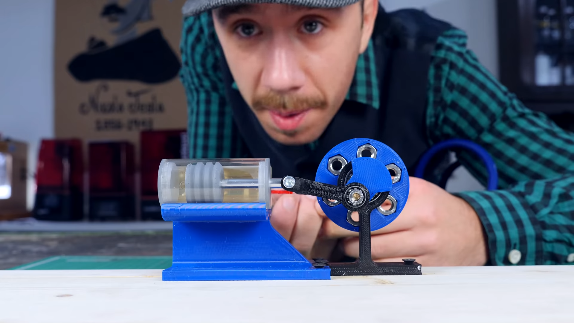
There are hobby projects that make you smile, and then there are hobby projects that make you stare at your 3D printer like it just earned a tiny engineering degree. A working reciprocating steam engine sits firmly in the second category. It has a piston, cylinder, crank, flywheel, valve gear, intake, exhaust, and just enough moving parts to make your printer whisper, “Please calibrate me before we embarrass ourselves.”
The wild part is this: yes, you can 3D print a working reciprocating steam engine. Not a decorative paperweight. Not a fake “engine-looking object” destined to gather dust beside your failed Benchy army. A real model engine can be printed, assembled, lubricated, and made to runoften first on compressed air, and in carefully controlled builds, on low-pressure steam.
But before anyone runs toward a pressure cooker with a roll of PLA and the confidence of a cartoon coyote, let’s be clear: printing a steam engine is not the same as printing a steam boiler. The engine is the moving mechanism. The boiler or steam source is the pressure vessel, and that is where safety stops being a suggestion and starts wearing steel-toed boots. This article explains how 3D printed reciprocating steam engines work, what materials make sense, what parts matter most, and why compressed-air testing should be your first victory lap.
What Is a Reciprocating Steam Engine?
A reciprocating steam engine converts pressure into motion. Steam enters a cylinder, pushes a piston, and then exits so the piston can move back again. That back-and-forth piston movement is called reciprocating motion. A connecting rod and crank convert that motion into rotation, which spins a flywheel. The flywheel stores momentum and helps carry the engine through the points in its rotation where the piston is not producing much force.
In classic steam engines, this basic idea powered pumps, mills, locomotives, ships, and early factories. In the 3D printing world, it powers something equally important: the maker’s irresistible need to say, “Look, it actually moves!”
The Key Parts
A 3D printed reciprocating steam engine usually includes the following components:
- Cylinder: The chamber where pressure acts on the piston.
- Piston: The sliding part that pressure pushes back and forth.
- Connecting rod: The link between piston and crank.
- Crankshaft: The rotating shaft that turns reciprocating motion into rotary motion.
- Flywheel: A heavy rotating wheel that smooths the engine’s movement.
- Slide valve or piston valve: The timing device that routes pressure to the correct side of the piston.
- Ports: Small passages that let air or steam enter and leave the cylinder.
- Frame and bearings: The structure that keeps everything aligned.
Of these parts, the valve system is the star of the show. Without a properly timed valve, the engine is just a tiny piston doing confused yoga.
How a Slide Valve Makes the Engine Run
Many printable steam engine designs use a slide valve because it is relatively simple, easy to understand, and delightfully mechanical. The slide valve moves back and forth over ports in the valve chest. As it moves, it opens one passage to admit pressure to one side of the piston while opening another path for exhaust. On the next half-turn, it swaps the flow so pressure enters the opposite side of the cylinder.
This alternating flow is what keeps the piston moving continuously. The valve is usually driven by an eccentric or offset crank connected to the flywheel. The timing is slightly ahead of the piston movement, often around a quarter turn, so pressure arrives at the right moment. When the timing is correct, the engine changes from “interesting assembly” to “chugging little miracle.”
That is also why small errors matter. A port that is too rough, a valve face that leaks, or an eccentric set at the wrong angle can stop the engine cold. Steam engines are not magical; they are just extremely honest. If something binds, leaks, or arrives late, the engine complains immediately.
Can You Really 3D Print One?
Yes, but with important qualifications. Makers have successfully printed working reciprocating engine models using resin printers and, in some cases, filament printers. Some run on compressed air. Some have been demonstrated on low-pressure steam. The most practical beginner goal is not “print a locomotive by dinner.” It is to print a model engine that runs smoothly on air, then decide whether steam operation is worth the additional safety and material challenges.
Compressed air is the friendly training wheels of model steam engineering. It lets you test valve timing, piston sealing, friction, leaks, and flywheel balance without heat, condensate, or boiler risk. If your engine will not run on air, steam will not magically fix it. Steam may add lubrication through condensation in some setups, but it also adds heat, water, expansion, sealing issues, and danger if the pressure source is poorly designed.
Best 3D Printing Methods for a Working Steam Engine
Resin Printing
Resin printing can produce smooth surfaces and fine details, which helps with cylinders, valve faces, ports, and small linkage parts. A resin-printed engine can look gorgeous, almost like a tiny museum piece that decided to become useful. The smoother surface finish can reduce sanding time compared with typical FDM parts.
However, not all resins are suitable for functional engine parts. Standard brittle resin may crack under stress, especially around screws, shafts, and thin connecting rods. Heat-resistant engineering resin is more appropriate for parts exposed to warmth, but even then, the builder should treat steam testing as an advanced step. Resin can be dimensionally precise, but it still needs washing, curing, support cleanup, and sometimes careful post-processing to achieve sliding fits.
FDM Printing
FDM printing is accessible, affordable, and perfect for prototypes, frames, flywheels, brackets, and educational engine models. PETG, ABS, ASA, nylon, and polycarbonate blends can be useful depending on the part. PLA is easy to print, but it is usually a poor choice for hot, loaded, or sliding engine parts because it softens at relatively low temperatures and can deform near heat sources.
FDM parts also have visible layer lines, and those layer lines can act like tiny speed bumps in cylinders and valve surfaces. A printed piston may need sanding, polishing, or a printed sleeve design. A cylinder bore may need reaming, honing, or redesigning with a liner. For a compressed-air model, FDM can work well if you design generous clearances, print carefully, and accept that post-processing is part of the project.
Hybrid Printing
The most reliable approach for many hobbyists is hybrid construction: print the complex shapes and use metal hardware where wear, heat, or alignment matters. That might mean metal rods for shafts, small bearings, brass tubing for ports, machine screws for pivots, O-rings for piston sealing, and a printed frame to hold everything together. This is not cheating. It is engineering with better manners.
Material Choice: What Should You Print It With?
Material selection depends on whether the engine is decorative, air-powered, or steam-tested.
For Display Models
PLA is fine for a display model or a hand-cranked educational cutaway. It prints cleanly, holds detail, and does not require an enclosure. If the model will never see heat or pressure, PLA can make a beautiful demonstration engine.
For Compressed-Air Engines
PETG is a strong everyday option for air-powered engine parts. It is tougher than PLA, less brittle, and more resistant to mild heat. ABS and ASA offer better heat resistance but are harder to print cleanly. Nylon is excellent for some moving parts because it is tough and has good wear behavior, but it absorbs moisture and usually needs careful drying before printing.
For Steam Exposure
Steam changes the game. Hot water vapor can soften plastics, swell materials, wash away lubricants, and expose weak printed layers. For any part that will directly contact steam, use a material specifically chosen for elevated temperature and moisture exposure. High-temperature resin, engineering-grade nylon, polycarbonate blends, or metal inserts may be necessary. Even then, the safest path is to keep steam pressure low, test behind shielding, and use a proper, rated steam source.
Design Details That Make or Break the Engine
Clearances
A CAD model with perfect zero-clearance fits is a beautiful lie. Real prints shrink, swell, elephant-foot, warp, and generally behave like tiny plastic divas. Moving parts need clearance. A piston must slide without wobbling too much. A valve must seal without binding. Shafts must rotate without chewing through their supports.
For FDM prints, many builders begin with roughly 0.2 to 0.5 mm of clearance for moving parts, then adjust based on printer calibration, material, and orientation. Resin printers can often achieve tighter fits, but resin parts still need real-world testing. A tolerance test print before the full engine can save hours of sanding and several dramatic sighs.
Surface Finish
Steam engines love smooth sliding surfaces. The piston, cylinder bore, valve face, and crank pivots all benefit from polishing. Sandpaper, small files, reamers, polishing compound, and patience are your friends. Patience is the one tool nobody wants to buy but everyone ends up needing.
Sealing
Leaks reduce power. In a small printed engine, even tiny leaks can matter because the available force is already limited. Builders often improve sealing with O-rings, light oil, silicone grease, polished valve faces, or carefully fitted pistons. A printed piston can work, but a piston with an O-ring groove is often more forgiving.
Alignment
The crankshaft, piston rod, cylinder, and valve gear must line up. A slightly crooked frame can create friction that overwhelms the engine. This is especially true in tiny engines, where available torque is small. Print orientation, screw tightening sequence, and frame stiffness all matter.
Why the Flywheel Matters More Than It Looks
The flywheel is not just a stylish spinning donut. It stores rotational energy and helps the engine move through dead centers, the points where the crank and connecting rod line up and produce little turning force. A heavier flywheel can make the engine run more smoothly, especially at low speed. Too heavy, however, and the engine may struggle to start.
For printed engines, a flywheel can be printed with infill adjusted for weight, designed with a metal ring, or built with embedded washers or hardware. Balance matters. A wobbly flywheel can shake the entire engine like a nervous washing machine.
Testing a 3D Printed Steam Engine on Compressed Air
Before using steam, test with compressed air. Start at low pressure. Add a few drops of light machine oil to sliding surfaces. Turn the flywheel by hand and listen for rubbing, scraping, or sudden stops. If it binds by hand, pressure will only make it bind with more enthusiasm.
Check the valve timing. If air enters the wrong side at the wrong time, the engine may rock back and forth instead of rotating. Adjust the eccentric or valve rod until the engine begins to self-cycle. Sometimes one tiny adjustment transforms the project from “dead crab” to “mini factory.”
Use short air bursts at first. Watch the piston, crank, valve, and flywheel. Look for leaks around the cylinder head, valve chest, and fittings. Tighten gently. Printed parts can crack if treated like cast iron, because they are not cast iron. They are plastic with dreams.
What About Running It on Real Steam?
A steam-powered printed engine is possible, but it should be approached as an advanced experiment. Steam adds heat and moisture, and the pressure source is the serious part. A model engine itself may be small, but a boiler or pressure vessel can store dangerous energy. Use a purpose-built, rated, inspected steam source with a pressure gauge, safety valve, and safe venting. Do not build a sealed boiler from random parts, mystery fittings, or “it held pressure once” optimism.
Many makers use compressed air because it demonstrates the engine beautifully without the hazards of boiling water under pressure. If you do run steam, keep pressures low, use shielding, wear eye protection, keep bystanders away, and never leave the system unattended. A working model engine is fun. A pressure accident is not a learning experience anyone needs.
Common Problems and Practical Fixes
The Engine Will Not Start
First, turn the flywheel by hand. If it feels gritty or tight, remove friction before changing anything else. Check that the piston is not too tight, the crankshaft is not misaligned, and the valve rod moves freely. Then confirm the valve timing. Many small engines fail because the valve opens late, early, or not enough.
The Engine Runs Only When You Flick the Flywheel
This often means friction is too high, pressure is too low, or the flywheel is too light. Polish the sliding parts, lubricate pivots, improve seals, and verify port openings. A slightly heavier flywheel may help the engine coast through dead centers.
Air Leaks Everywhere
Inspect mating surfaces. Printed valve covers and cylinder heads may need flat sanding on a piece of glass or another known-flat surface. Add gaskets made from thin silicone sheet, paper, or suitable sealant depending on temperature. Do not overtighten screws into printed plastic.
The Piston Sticks After a Few Seconds
Heat, swelling, poor lubrication, or an overly tight bore can cause sticking. Increase clearance, use a better material, polish the bore, or redesign the piston with an O-ring. If testing with steam, condensation may also collect and create drag or hydraulic resistance.
Why This Project Is Worth Building
A 3D printed reciprocating steam engine is one of the best projects for learning mechanical systems because it makes invisible principles visible. You can see timing. You can feel friction. You can hear leaks. You can watch pressure become motion, then rotation, then momentum. It is thermodynamics, manufacturing, materials science, and old-school machinery packed into a desk-sized contraption that makes extremely satisfying little chuffing noises.
It also teaches a lesson that every maker eventually learns: printing the part is only half the project. The other half is fitting, sanding, adjusting, lubricating, reprinting, and pretending the first version was “just a prototype” all along.
Recommended Build Approach for Beginners
If you want the best chance of success, start with an established 3D printable air or steam engine model. Choose one with assembly photos, a bill of materials, and comments from other builders. Print the frame and non-contact parts first. Then print tolerance-sensitive parts such as the piston, cylinder, and valve chest. Test-fit everything before final assembly.
Use metal shafts if the design allows it. Add bushings or bearings where possible. Print spare pistons and valves because these parts may need tuning. Keep a small notebook of changes: nozzle size, layer height, material, clearance, print orientation, and what worked. Future you will thank present you. Future you is usually holding sandpaper and wondering what past you was thinking.
Advanced Upgrades
Once the engine runs, there are many ways to improve it. You can redesign the flywheel, add bearings, use a transparent cylinder, print a cutaway valve chest, add a tachometer, mount the engine on a display base, or connect it to a tiny generator. You can also compare performance on compressed air versus low-pressure steam, measuring run speed, startup pressure, and temperature effects.
For educational use, a printed engine can become a classroom demonstration of pressure, energy conversion, valve timing, crank geometry, and design-for-manufacturing. It is far more memorable than a diagram alone. A diagram says “reciprocating motion.” A printed engine says “watch this piston do push-ups until the flywheel wakes up.”
Experience Notes: What Building One Actually Feels Like
The first experience most builders have with a 3D printed reciprocating steam engine is not triumph. It is suspicion. You assemble the parts, spin the flywheel, connect air, and the engine responds with a tiny hiss and absolutely no movement. This is normal. Small engines are dramatic. They want attention. They want alignment. They want surfaces smoother than your first print is willing to provide.
On a practical build, the cylinder and valve face usually demand the most patience. Even when a print looks clean, the surface may have tiny ridges that leak pressure or create drag. Light sanding can make a shocking difference. A piston that felt “pretty good” may become excellent after polishing and oiling. A slide valve that barely moved may suddenly glide after the support marks are removed. The lesson is simple: mechanical prints are not judged by how they look on the build plate; they are judged by how they move after cleanup.
Another common experience is learning that screws can be villains. Tighten a frame screw too much and the crankshaft may bind. Tighten a valve chest unevenly and the slide valve may jam. Leave things too loose and pressure escapes like gossip in a small town. The sweet spot is firm, square, and aligned. When in doubt, loosen the assembly, rotate the flywheel, and tighten gradually while checking motion after each step.
Compressed-air testing is where the project becomes addictive. At first, the engine may need a finger flick. Then it runs for half a second. Then you adjust the eccentric and it runs for five seconds. Then you add oil, reduce friction, and suddenly it is spinning steadily on the bench. That moment feels absurdly rewarding. Nothing about the engine is mysterious anymore: you can see every part doing its job, and you can also see exactly which part is lying.
Steam testing, if attempted, feels different. It is slower, wetter, and more serious. Condensation appears. Parts warm up. Lubrication changes. The engine may run with a softer sound, but the setup demands respect. The safest builders treat steam as a controlled demonstration, not a casual party trick. They use rated equipment, pressure gauges, relief valves, shielding, and low pressure. They test with air first, fix every leak first, and do not improvise pressure vessels.
The best personal takeaway from this kind of project is that 3D printing is not only for static objects. It can produce working mechanisms, but only when the designer respects tolerances, materials, heat, friction, and assembly. A printed steam engine is a small machine with a big personality. It rewards careful calibration and punishes wishful thinking. In other words, it is the perfect maker project: educational, slightly ridiculous, and deeply satisfying when it finally chugs to life.
Conclusion
You can 3D print a working reciprocating steam engine, and the project is a fantastic blend of old technology and modern fabrication. The engine works by routing pressure through a valve system that alternately drives a piston, while the crank and flywheel convert back-and-forth motion into smooth rotation. Resin printing, FDM printing, and hybrid construction can all play a role, but material choice and post-processing matter enormously.
For most builders, the smartest path is to print a proven design, test it on compressed air, improve sealing and timing, then consider whether live steam is truly necessary. If steam is involved, safety must come first: use proper pressure-rated equipment, relief valves, gauges, shielding, and common sense. A tiny printed engine can teach huge lessons, but only if the builder respects pressure, heat, and the limits of plastic.
Note: This article is for educational and model-engineering purposes only. Do not fabricate or operate homemade boilers or pressure vessels without proper design, rated components, testing, and applicable safety compliance.