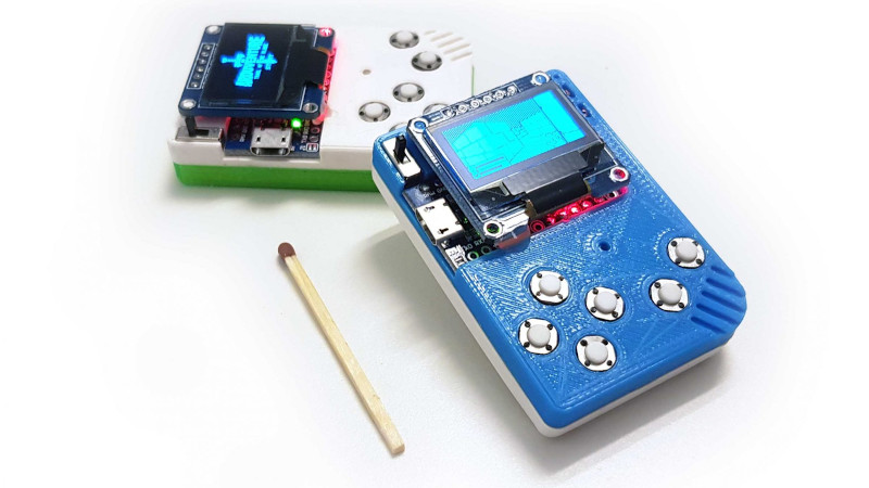
There are maker projects that make you nod politely, and then there are maker projects that make you squint at the screen and say, “Wait, you did what with the plastic?” A PCB-free Arduboy falls firmly into the second category. Instead of treating a 3D printer as a machine that spits out a nice-looking case after the electronics are done, this approach turns the print itself into part of the electrical design. The result is a handheld game device that behaves like an Arduboy, looks like a tiny retro console, and routes its wires through printed channels rather than a traditional printed circuit board.
That is the hook behind the now-famous “Arduboy minus the PCB” idea: use 3D printing for wire paths so the enclosure becomes a guide, a fixture, and a structural support for the electronics. It is not quite a breadboard, not quite perfboard, and definitely not a factory-ready PCB. It is something delightfully in-between. And for makers, educators, and tinkerers who enjoy squeezing maximum cleverness out of minimal parts, it is the kind of project that feels both practical and slightly mischievous. In the best possible way.
More importantly, this build is not just a novelty. It points to a smarter way of thinking about low-cost handheld electronics, especially when the design is simple, the component placement is predictable, and the goal is fast iteration rather than mass production. If a circuit is modest enough, and if the enclosure can hold every switch, display, and module in the right spot, the plastic body can do a surprising amount of the organizational work a PCB usually handles.
Why This PCB-Free Arduboy Idea Gets So Much Attention
The original Arduboy already has a lot going for it. It is tiny, open source, friendly to hobbyist development, and built around approachable hardware: an ATmega32U4 microcontroller, a monochrome OLED display, buttons, and a buzzer. That means it lives in the sweet spot between toy and development platform. It can run games, but it also teaches constraints, optimization, and hardware awareness. In other words, it is catnip for the maker crowd.
So when someone figures out a way to remove the PCB and still keep the handheld experience intact, people notice. The “3DPCBoy” style build is compelling because it takes the familiar Arduboy formula and strips it down to the essence: a microcontroller board, a small SPI OLED, six buttons, a simple speaker, battery power, and careful wiring. No custom board order. No waiting for fab turnaround. No “version three will fix the footprint mistake” drama. Just parts, plastic, copper, patience, and a soldering iron that behaves itself for once.
That is the real magic here. The project does not try to out-spec the Arduboy. It tries to out-smart the usual prototyping path.
What The Original Arduboy Hardware Makes Possible
A tiny but capable gaming platform
The Arduboy platform works because its hardware is disciplined. The ATmega32U4 is not a powerhouse by modern handheld standards, but it is exactly the kind of chip that rewards good engineering habits. It has enough flash, enough RAM for compact games, built-in USB support, and a long history in Arduino-compatible boards. That means developers get a microcontroller that is familiar, well-documented, and small enough to fit the “pocket console” dream without turning the battery into a lunchbox.
Paired with a 128×64 monochrome OLED, the setup forces a kind of design honesty. There is no hiding behind flashy graphics or memory-heavy artwork. Games have to be clever, readable, and efficient. This is one reason Arduboy remains so beloved. It feels constrained in a fun way, like writing haiku on a skateboard.
Why off-the-shelf parts are a big deal
The PCB-free version matters because the core Arduboy recipe can be rebuilt from common modules. Instead of a custom board, makers can use an Arduino Pro Micro–style board, a small SPI OLED breakout, tactile switches, thin copper wire, and a simple battery setup. Once those parts are arranged in fixed positions, the wiring no longer has to float around like spaghetti that lost the will to live. It can follow printed grooves.
That modularity is the entire reason the idea works. If the display, controls, and microcontroller all had weird shapes or unpredictable mounting needs, this would be a frustrating craft project with a body count. But because the component choices are straightforward and the layout is repeatable, the 3D-printed body becomes a reliable mechanical map.
How 3D Printing For Wire Paths Replaces Part Of The PCB’s Job
The enclosure becomes the routing guide
A conventional PCB does several jobs at once. It provides electrical connections, physically supports parts, locks in spacing, and helps keep everything repeatable. In this build, the printed shell borrows two of those jobs very effectively: positioning and mechanical support. The wire channels handle part of the third job by telling each conductor exactly where to go.
That is why the project looks so elegant. The wires are not just stuffed into a box and told to figure things out. They are routed through grooves that mimic old-school hand-laid traces. The print has cutouts for the buttons, a slot for the microcontroller board, holes for threading wires, and space for the display and battery hardware. Suddenly, point-to-point wiring stops looking like a panic response and starts looking intentional.
For beginners, this is huge. One of the hardest parts of hand wiring is not the soldering itself. It is keeping track of physical organization so the build remains serviceable. Printed wire paths solve that problem by turning layout into geometry.
Why this works best with short, simple connections
There is a reason this method shines in compact handhelds instead of, say, a laptop motherboard. The signal count is limited, the distances are short, and the functions are clear. A handful of button lines, a display connection, ground, power, speaker output, and maybe a switch or LED are manageable. Once you start piling on dense routing, higher speeds, or lots of components, a real PCB wins by a country mile.
Display choice also matters. Small OLED modules that support SPI are a natural fit because SPI is commonly used in compact embedded builds where quick updates and predictable wiring are important. The moment you can keep the display wiring short and direct, life becomes much easier. The project stops being an improvised nest and starts feeling like a legitimate product prototype.
Why Makers Love This Approach
It is cheaper, faster, and more teachable
A custom PCB is wonderful when you know the design is stable. But when you are experimenting, teaching, or building only one or two units, a board can be overkill. The PCB-free Arduboy sidesteps that. If the shell is designed well, you can print the front piece, gather common components, and assemble the console without commissioning a board house at all.
That lowers the barrier in three ways. First, it saves money on tiny runs. Second, it speeds up iteration because case revisions can happen right in CAD and on the printer. Third, it makes the circuit more visible. A PCB hides a lot of logic inside copper layers and traces. A routed-wire design puts the structure in plain sight. For education, that is gold. Students can literally see which button wire goes where, where ground is shared, how the display is connected, and why clean routing matters.
There is also a psychological win here. A project like this feels more achievable than a full custom electronics manufacturing workflow. It invites experimentation. Swap a button. Rework a channel. Adjust the case. Reprint. Try again. That cycle is very maker-friendly.
It lands in the sweet spot between breadboard and PCB
Breadboards are fantastic for fast testing, but they are terrible roommates. They take up space, pop loose at the worst times, and turn portable projects into fragile desk sculptures. A proper PCB fixes all that, but it takes planning, tools, and lead time. The printed-wire-path method sits right in the middle. It is more permanent than a breadboard, more physically coherent than perfboard in some cases, and much quicker to revise than a manufactured board.
That “middle lane” is what makes this idea broader than one cute handheld. The same logic could apply to remotes, test tools, simple sensor nodes, educational kits, or one-off interfaces where the enclosure shape matters as much as the circuit itself.
Where A Real PCB Still Wins Fair And Square
Repeatability, durability, and scale
Let us be fair to the humble PCB, because it has earned the right to smirk. Printed circuit boards are still the foundation of modern electronics for good reasons: consistent routing, compact density, repeatable assembly, strong solder joints, predictable performance, and easier manufacturing at scale. If you want to make dozens, hundreds, or thousands of devices, a tangle-free hand-wired print is charming, but a PCB is civilization.
PCBs also handle abuse better over time. Routed wires can be neat, but they are still individual conductors. They can be nicked, stressed, or mis-soldered. Repairs are possible, but so are surprises. A board reduces that uncertainty by locking the electrical layout into something stable and reproducible.
Electrical complexity changes the conversation fast
Once designs get denser, faster, or more sensitive, the PCB-free method runs into reality. Fine-pitch parts, tight timing, noise management, and complex grounding all push you back toward formal board design. Even enclosure experts emphasize the importance of tolerances, connector clearances, and accurate component measurements before parts ever go into a case. The more complicated the system, the more those details stack up.
So no, a 3D-printed wire-path handheld is not “the end of PCBs.” It is a clever alternative for a narrow but meaningful category of projects. And that is more than enough.
What This Project Says About The Future Of DIY Electronics
One of the most interesting things about this Arduboy-style build is how closely it echoes larger industry ideas. Engineers have long chased ways to merge electronics and structure more tightly, whether through molded interconnect devices, integrated mechanical-electrical workflows, or smarter CAD-to-prototype pipelines. This little handheld is not a production MID, of course, but it points in the same philosophical direction: the enclosure is not an afterthought. It is part of the system.
That shift matters. As 3D printing gets better and CAD tools become more accessible, makers are increasingly free to treat shape, fit, routing, and user interaction as one design problem instead of four separate headaches. In that world, a project like this is not a gimmick. It is a preview of how hobby electronics can become more elegant without becoming more intimidating.
And frankly, there is something deeply satisfying about using plastic to boss copper around. The wires get tiny roads. The buttons get assigned seats. The microcontroller gets a snug little apartment. Everybody behaves. For once.
The Build Experience: What It Actually Feels Like To Make A PCB-Free Arduboy
If you have never built a handheld this way, the experience is half electronics project and half tiny mechanical puzzle. The first surprise is that the printed front shell does not feel like a “case” in the usual sense. It feels more like a tray, a jig, and a wiring diagram that escaped from your CAD program and became physical. Once the buttons drop into their pockets and the microcontroller board slides into its slot, you immediately understand why the idea works. The layout is no longer abstract. It is sitting in your hand, quietly demanding neat soldering.
The second surprise is how much the project changes your relationship with wire. On a breadboard, jumpers are cheap and lazy. On a PCB, traces are invisible once the board is made. But here, every conductor becomes part of the product’s visual logic. You cut it carefully. You bend it with intent. You thread it through holes and tuck it into channels, and suddenly even a simple ground run feels like architecture. It is oddly satisfying, like making miniature roads for electricity and then pretending that was always a normal Saturday activity.
There is also a healthy amount of suspense. When you solder near a printed part, you become very aware that plastic and heat have a complicated relationship. Too little heat, and you get weak joints. Too much, and your elegant little groove becomes modern art. So the build teaches restraint. Quick joints matter. Clean tip, steady hand, no dramatic solder blobs, no heroic speeches. Just precision.
Then comes the button-testing stage, which is where many makers experience the emotional range of an entire sports season in about three minutes. One button works. Great. Two buttons work. Amazing. The third does nothing, and now you are bargaining with the universe. Usually it turns out to be a cold joint, a wire not fully seated, or a grounding issue. The good news is that because the wiring is visible and organized, troubleshooting feels less like archaeology and more like detective work.
Mounting the OLED is another memorable moment. A small monochrome screen suddenly makes the whole build feel real. Before that, it is a charming skeleton. After that, it becomes a handheld console with opinions. Once the display lights up and the buzzer chirps, the project stops being “a bunch of parts in a printed shell” and becomes an actual game machine. That transition is ridiculously motivating.
What many makers love most, though, is the sense of direct ownership. A standard PCB build can feel polished, but it can also feel distant, as if the intelligence lives in the board order and assembly files. A wire-path build feels personal. You know every route because you placed every route. You know why the switch sits where it sits because you designed the pocket or printed the part that holds it there. The final device is not just assembled; it is composed.
And yes, there is a little bit of chaos in the process. A channel may be too tight. A wire may need rerouting. A battery lead may behave like it was raised by wolves. But that is part of the charm. This kind of project gives you the satisfying sense that you are inventing alongside the build, not merely following instructions. By the time a game finally boots on a handheld with no custom PCB inside, the victory feels deliciously disproportionate. It is a tiny monochrome machine, but the maker grin it produces is full size.
Conclusion
“3D Printing For Wire Paths Yields An Arduboy Minus The PCB” is more than a catchy description for a clever hack. It is a sharp little lesson in design thinking. By letting the printed body do some of the heavy lifting that a board normally handles, makers can build a handheld that is cheap, understandable, compact, and surprisingly refined. The technique will not replace traditional PCB design, and it should not try to. But for simple electronics, learning projects, low-volume builds, and wonderfully nerdy handhelds, it opens a genuinely useful path.
That is why the project sticks in people’s minds. It reframes the role of 3D printing from “make the box later” to “help define the circuit now.” It keeps the joy of open-source handheld gaming intact while showing that hardware layout can be inventive, visible, and even a little artistic. For makers, that is the real prize. Not just building an Arduboy-like device without a PCB, but building one in a way that makes the whole design process easier to understand and a lot more fun to explore.